Density Variation and Solidification in Metal Casting
A deep-dive into the physics of phase change, shrinkage mechanics, microstructural evolution, and modern computational approaches that define the science and engineering of metal casting solidification.
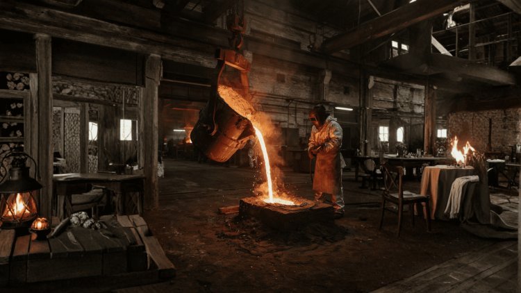
The Density Challenge:
Why Metals Shrink
One of the most fundamental challenges in metal casting is the inherent density difference between the liquid and solid phases of a metal. Understanding and compensating for this difference is essential to producing sound, defect-free castings.
Solidification Changes Volume
Solid vs. Liquid Density
The solid phase of most metals is significantly denser than the liquid phase from which it forms. This means that as a casting solidifies, the same mass of metal occupies a smaller volume.
This volumetric reduction per unit weight is the root cause of shrinkage voids, including internal cavities and surface depressions that form when liquid metal is no longer available to feed the contracting solid.
Different Metals, Different Shrinkage
How Shrinkage Voids Develop
The Cast Iron Exception
Natural Shrinkage Compensation
This self-compensating behavior makes gray and ductile iron especially attractive for complex castings where feeding is difficult, since graphite expansion can naturally suppress void formation.
Patternmaker's Shrinkage Allowance
To account for the predictable shrinkage of a given alloy, patternmakers systematically oversized the mold cavity relative to the desired final part dimensions.
These shrinkage allowances, typically expressed in millimeters per meter or as a percentage, are alloy-specific and must be applied carefully. Incorrect allowances lead to parts that are either undersized or require excessive machining, adding cost and waste to the manufacturing process.
Start Larger to Finish Correctly
Insufficient dimensional compensation can produce finished castings that fall below required dimensions after cooling.
Excessive compensation increases machining stock, material consumption, processing time, cost, and waste.
Modern pattern design often incorporates computer-aided simulation to validate shrinkage compensation before physical tooling is produced.
Feeding and Compensation Protect the Casting
Successful casting design requires engineers to understand both the volumetric changes occurring during phase transformation and the predictable dimensional contraction that continues as the casting cools.
Shrinkage Is Not A Defect.
Uncompensated Shrinkage Is.
Most metals naturally become denser as they solidify, causing the same mass of material to occupy less volume. Aluminum may contract approximately 6–7% volumetrically during solidification, while steel can contract by roughly 2–4%. If liquid feeding is interrupted, this volume reduction produces internal shrinkage cavities or surface depressions. High-carbon cast irons provide an important exception because graphite precipitation generates volumetric expansion that can partially or completely compensate for normal solidification shrinkage. Beyond internal feeding, predictable dimensional contraction must also be addressed through alloy-specific patternmaker's shrinkage allowances. Modern simulation provides the ability to validate both feeding behavior and dimensional compensation digitally before physical tooling is produced.
The transformation from liquid metal to solid is governed by well-established thermodynamic and heat-transfer principles. Understanding these mechanisms allows engineers to predict and control the solidification behavior of complex castings with increasing precision.
From a fully molten metal to a completely solid casting.
Above liquidus; fully molten.
Between liquidus and solidus; partial solid.
Below solidus; fully solidified.
Pure metals solidify at a single, well-defined freezing point — the liquidus and solidus temperatures are identical. When the melt reaches this temperature, a sharp solid-liquid interface advances through the casting.
In contrast, commercial alloys solidify over a temperature range defined by the liquidus (the temperature at which solidification begins) and the solidus (the temperature at which it is complete). Between these two temperatures, the metal exists in a semi-solid “mushy zone,” a mixture of solid dendrites and interdendritic liquid. The width of this mushy zone has profound implications for feeding behavior, segregation, and hot tearing susceptibility.
The rate at which heat is extracted from the melt into the surrounding mold governs the progression of solidification. Early in the process, a solid “skin” or shell forms at the mold wall where cooling is most intense. The shell thickens progressively as heat continues to conduct outward.
The mold material’s thermal resistance influences how rapidly heat is extracted.
The gap that develops between casting and mold wall affects heat transfer.
Heat released during phase change also affects the advance of the solidification front.
Relatively low thermal conductivity results in slower cooling and coarser microstructures.
Extracts heat much more rapidly than a sand mold.
A foundational relationship in casting engineering, Chvorinov’s Rule states that the total solidification time t is proportional to the square of the volume-to-surface area ratio (V/A)² of the casting, scaled by a mold constant B.
This relationship captures the physical reality that thicker sections take longer to solidify, since they have more volume to cool relative to their heat-dissipating surface area. It is widely used to size risers and predict relative solidification sequences within a casting.
Solidification time depends on the mold constant and the square of the casting’s volume-to-surface-area ratio.
Understanding freezing ranges, heat extraction, shell formation, and solidification time provides engineers with a physics-based foundation for analyzing casting behavior and planning riser design and solidification sequences.
The Physics of Phase Change
Three States During Solidification
Liquid Metal
Mushy Zone
Solid Casting
Pure Metals vs. Alloys
Heat Transfer and Shell Formation
Mold Thermal Resistance
Interfacial Gap
Latent Heat
How Mold Material Changes Cooling
Chvorinov’s Rule
From Phase Change to Predictable Casting
Achieving a sound, void-free casting requires more than simply filling a mold with liquid metal. The manner in which the metal solidifies—the sequence, direction, and rate—must be carefully engineered to ensure that liquid metal is always available to feed shrinking solid regions.
The fundamental objective is to ensure that solidification proceeds progressively from the most remote regions of the casting toward the riser—the reservoir of liquid metal attached to the casting. This "directional" sequence ensures that as each region contracts, liquid metal from a still-molten upstream zone can flow in to compensate.
A riser must remain liquid longer than any portion of the casting it is intended to feed. By Chvorinov's Rule, this means the riser must have a higher volume-to-surface area ratio than the section it feeds. Risers are classified as open (vented to atmosphere) or blind (enclosed), and as top-risers or side-risers depending on their position relative to the casting.
Chills are inserts or liners placed in or against the mold to locally accelerate heat extraction and cause specific zones to solidify earlier than they otherwise would. External chills are placed on the mold wall adjacent to a heavy section, drawing heat through the wall more rapidly. Internal chills are metal inserts placed directly within the mold cavity; they absorb heat from the surrounding melt and fuse with the casting.
The physical orientation of the casting within the mold has a decisive influence on solidification sequence. By positioning the heaviest sections—which solidify last—highest in the mold and closest to the riser, gravity assists the downward flow of liquid metal to feed contracting regions.
Controlling the Front:
Directional SolidificationProgressive solidification from remote regions toward the riser.
Keep the riser liquid longer than the casting.
Accelerate solidification where needed.
Use gravity and geometry to assist feeding.
—is the cornerstone of sound, void-free casting design.
The microstructure that forms during solidification—grain morphology, dendrite architecture, and compositional distribution—ultimately determines the mechanical and physical properties of the finished casting. These features are governed by the interplay of thermodynamics, solute diffusion, and local cooling conditions.
As solidification proceeds in an alloy, solute atoms are rejected from the growing solid into the adjacent liquid. This enriches the liquid immediately ahead of the solid–liquid interface with solute, which depresses the local liquidus temperature. If the actual temperature in the liquid falls below this locally depressed liquidus—a condition known as constitutional undercooling—the planar solid–liquid interface becomes thermodynamically unstable.
The partitioning of solute between solid and liquid phases is described by the equilibrium partition coefficient \(k = C_s / C_l\), where \(C_s\) and \(C_l\) are the solute concentrations in the solid and liquid at the interface. For most engineering alloys, \(k < 1\), meaning solute preferentially remains in the liquid. As the solid grows, solute continuously builds up at the interface, creating a concentration boundary layer in the liquid.
Once the interface breaks down into dendrites, solidification proceeds through the growth of tree-like crystal structures with a primary trunk and branching secondary (and sometimes tertiary) arms. The primary dendrite arm spacing (PDAS) and secondary dendrite arm spacing (SDAS) are inversely related to the local cooling rate: rapid cooling produces fine dendrites, while slow cooling yields coarse ones.
Because solute diffusion in the solid is very slow at typical casting cooling rates, the compositional gradients established during solidification are largely "frozen in" to the microstructure. The result is microsegregation—the dendrite cores are depleted in solute relative to the interdendritic regions, which are correspondingly enriched.
Microstructure and
Solute RedistributionPlanar front → cellular → dendritic.
Partitioning drives microsegregation.
Cooling rate sets dendrite arm spacing.
Compositional gradients "frozen in".
solute partitioning, dendritic growth kinetics, and microsegregation
—ultimately determines the mechanical and physical properties of the finished casting.
As casting applications push into ever more demanding structural and aerospace environments, the tolerance for defects narrows and the need for predictive, simulation-driven process design intensifies. Modern casting science addresses both the characterization of complex defect mechanisms and the development of sophisticated numerical tools to eliminate them before metal is ever poured.
Unlike microsegregation, which operates at the dendrite scale, macrosegregation produces compositional non-uniformity across the entire cross-section of a casting, over distances ranging from centimeters to meters.
It arises from the large-scale flow of solute-enriched interdendritic liquid driven by shrinkage, thermal and solutal buoyancy, and deformation of the solid network. In large steel ingots, macrosegregation can render entire regions of the casting off-specification, leading to costly rejection or extensive downstream processing.
Controlling macrosegregation requires careful management of casting geometry, solidification rate, and electromagnetic or mechanical stirring in continuous casting operations.
Modern Frontiers:
Defects and Numerical ModelingFrom Casting-Scale Defects to Engineered Microstructure
Macrosegregation
What Drives Macrosegregation?
Manage Large-Scale Mass Transport
Inverse Segregation &
Meniscus Freezing
What's Your Reaction?