Precision in Metal: Simulating Ductile Iron Solidification
A deep dive into the cutting-edge computational methods, multiscale models, and experimental validation techniques that are transforming how engineers design, predict, and optimize ductile iron castings — from the molecular level to the foundry floor.
The Hidden Complexity
of Ductile Iron
Ductile iron, also known as nodular or spheroidal graphite iron, is one of the most important engineering materials in heavy industry. Although widely used, its solidification behavior is remarkably complex. Achieving the desired balance of strength, ductility, durability, and castability requires precise control over chemistry, inoculation practice, temperature, cooling rate, and graphite evolution throughout the solidification process.
Three Critical Challenges
Dual-Phase Competition
Unlike many engineering alloys that solidify through comparatively straightforward phase evolution, ductile iron undergoes simultaneous growth of graphite nodules and austenite shells. These two phases continuously interact during solidification, influencing carbon diffusion, local chemistry, and final microstructure.
Successful production depends on maintaining graphite as nearly perfect spheroidal nodules. Any shift toward flake graphite, chunky graphite, or degenerated graphite morphologies can severely reduce toughness, ductility, and fatigue resistance.
Simultaneous Phase Development
Critical Graphite Control Factors
The Importance of the Austenite Shell
The austenite shell surrounding each graphite nodule regulates carbon diffusion during solidification and ultimately controls the final graphite volume fraction. Poor management of the graphite-austenite interface increases susceptibility to carbide formation, shrinkage porosity, and internal defects that are often undetectable through visual inspection alone.
Thin-Wall Casting Challenges
The increasing demand for lightweight components in automotive and aerospace applications pushes ductile iron foundries toward thinner wall sections. These geometries introduce dramatically higher cooling rates, compressing the available solidification window and making graphite spheroidization significantly more difficult.
When solidification occurs too rapidly, the system may not provide sufficient time for graphite nodules to fully develop, increasing the likelihood of defect formation and undesirable microstructural transformations.
Elevated Thin-Wall Defect Risks
Internal Microporosity
Formed by dissolved gas rejection and restricted feeding during rapid solidification.
Hot Tearing & Cold Cracking
Driven by steep thermal gradients and high contraction stresses.
Carbide Formation
Rapid eutectic transformation increases the risk of hard and brittle carbides.
Macrosegregation
Alloying elements redistribute unevenly across the casting section.
Smaller Processing Window
As wall thickness decreases, the tolerance for temperature variation, chemistry imbalance, and inoculation inconsistency becomes significantly smaller.
Why Simulation Is Essential
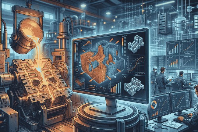
Traditional trial-and-error foundry development struggles to manage the enormous number of interacting variables governing ductile iron solidification. Chemistry, thermal gradients, mold design, inoculation effectiveness, graphite nucleation behavior, and feeding conditions all influence final quality simultaneously.
Modern simulation platforms allow engineers to explore these interactions digitally, reducing development time while improving confidence in casting integrity, dimensional accuracy, and mechanical performance.
Simulation Enables Prediction Of
Interacting Variables
Control The Casting
The shape, distribution, and growth behavior of graphite nodules ultimately determine whether ductile iron achieves its remarkable combination of strength, toughness, and reliability.
Ductile Iron Appears Simple.
Its Solidification Behavior
Is Anything But.
The outstanding engineering performance of ductile iron originates from a highly sensitive solidification process involving simultaneous graphite and austenite development. Maintaining spheroidal graphite morphology while preventing carbides, porosity, segregation, and cracking requires precise control over chemistry, inoculation practice, thermal history, and cooling conditions. These challenges become even more severe in thin-wall castings where rapid solidification limits the time available for proper graphite evolution. As a result, computational simulation has evolved from a useful engineering aid into an essential tool for predicting microstructure, managing risk, and ensuring consistent production-quality ductile iron castings.
Researchers now connect macro-scale mold filling with micro-scale grain evolution through hierarchically coupled solvers. Macro models capture bulk flow, pressure, and global temperature fields, while micro-scale solvers resolve grain nucleation and growth events.
The coupled Finite Element Method and Cellular Automata approach combines continuum-scale thermal and mechanical fields with discrete grain-scale nucleation and growth behavior.
Handles continuum-scale thermal and mechanical fields with high fidelity, solving the heat equation across complex 3D geometries with millions of degrees of freedom.
Operates on a discrete lattice overlaid on the FEM mesh, with cells evolving according to local thermodynamic rules for nucleation probability and growth velocity.
Coupled FEM-CA simulation enables engineers to predict the spatial distribution of ferrite and pearlite phases throughout the final casting and evaluate whether desired mechanical properties can be achieved consistently across production batches.
By connecting process-scale physics with microstructural evolution, multiscale simulation creates a computational bridge from casting conditions to the final performance of ductile iron.
From Atoms to Meter-Scale Castings
From Macro to Micro: Bridging the Gap
Global Casting Behavior
Grain-Level Evolution
Why Two-Way Coupling Matters
FEM and Cellular Automata
Finite Element Method
Cellular Automata
One Mesh, Two Levels of Resolution
From Grain Evolution to Mechanical Performance
Simulation Outputs That Inform Production
Connecting Microstructure to Performance
High-resolution XCT generates 3D digital replicas of microstructures with sub-micron resolution. Unlike 2D metallography, XCT captures true morphology of nodules, porosity networks, and grain boundaries without destructive sectioning. These replicas validate CA model predictions, enable voxel-based FEM simulations, and provide critical parameters like nodule density and sphericity. Synchrotron XCT even allows real-time observation of solidification dynamics.
Surrogate models reduce weeks of HPC computation to minutes by learning input-output relationships from training runs. They enable rapid parametric studies and uncertainty quantification. Inverse modeling matches simulated stress-strain curves to experimental data, extracting constitutive parameters for ferrite, pearlite, and carbides. This makes industrial-scale ductile iron solidification studies economically feasible for the first time.
Together, high-resolution XCT and surrogate modeling transform casting simulation into a validated, efficient, and scalable process — bridging experimental fidelity with computational speed.
Accelerating Simulation Validation & Deployment
X-Ray Tomography: Digital Twin of Microstructure
Surrogate Models: Compressing Complexity
The true value of computational casting science is measured not in research papers but in foundry performance. Modern simulation platforms have successfully translated decades of thermodynamics, fluid mechanics, solidification theory, and materials science into practical engineering tools that can be used directly on the production floor. Today, simulation is no longer an experimental technology. It is a proven industrial capability that reduces scrap, improves quality, shortens development cycles, and delivers measurable financial returns.
Industrial software environments such as MAGMASOFT and ProCAST have transformed simulation from an academic exercise into a daily engineering tool. These platforms combine mold filling analysis, solidification modeling, stress prediction, phase transformation calculations, and defect forecasting within a unified workflow.
Engineers can now evaluate and optimize casting processes digitally before tool construction, significantly reducing development risk and minimizing costly production corrections.
Prevents metal splashing, air entrapment, oxide formation, and filling instabilities during pouring.
Identifies shrinkage and gas defects in critical automotive and industrial components before production.
Ensures adequate liquid metal supply to late-solidifying hot spots and thermal centers.
Optimizes chills, mold coatings, and cooling pathways to achieve target microstructures.
A documented automotive differential housing project used MAGMASOFT-guided gating redesign to reduce porosity-related scrap rates from more than 12% to less than 2%, generating substantial annual cost savings.
Simulation confidence is earned through validation. Predicted behavior must consistently match measurements obtained from physical castings. Thermal analysis remains one of the most important validation methods because it directly reflects the underlying thermodynamics and solidification kinetics driving the process.
Accurate prediction of eutectic arrest temperature, recalescence behavior, cooling rate, and final solidification time demonstrates that the simulation model has been correctly calibrated for industrial use.
Real-World Impact:
Optimizing Industrial ProductionThree Foundations of Industrial Success
Commercial Simulation Platforms in Action
Core Industrial Applications
Gating & Riser Optimization
Porosity Prediction
Feeding System Design
Cooling Control
Scrap Reduction Through Simulation
Validation and Measured Success
Critical Thermal Validation Targets
Next-generation integrated computational materials engineering (ICME) frameworks aim to connect the physics of solidification directly to in-service component behavior — creating a continuous Process → Structure → Property → Performance linkage.
Multiscale models can predict fatigue life, crack initiation sites, and crack propagation paths throughout the service life of industrial components.
By importing simulated microstructure geometry into Crystal Plasticity Finite Element (CPFE) solvers, engineers can evaluate individual nodule-matrix interfaces and predict where cracks may nucleate and how they propagate through pearlite-ferrite matrices under prescribed loading spectra.
Mastering melt physics and coupling it with machine-learning-enhanced surrogate models and real-time sensor data is shifting foundries from reactive manufacturing toward proactive, data-driven engineering.
The PSPP Vision
Fatigue & Crack
Propagation PredictionData-Driven,
Proactive ManufacturingReactive → Predictive → Proactive
What's Your Reaction?