Modeling Alloy Shrinkage Behavior During Cooling
A deep-dive into the physics, mathematics, and engineering strategies behind one of metallurgy's most critical manufacturing challenges — from the moment metal is poured to the final solid casting.
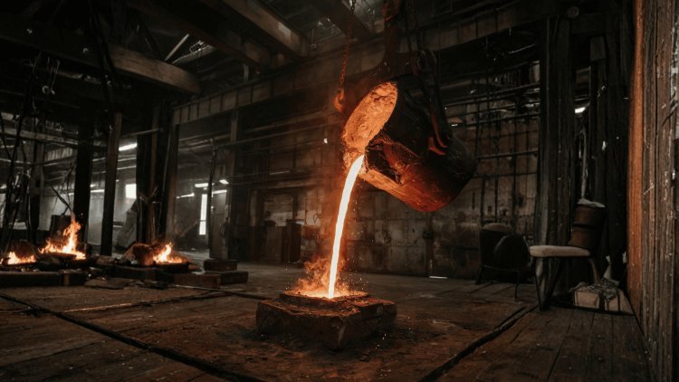
The Shrinkage
Challenge
Shrinkage is not a single phenomenon — it is a cascade of volumetric losses that occur at distinct stages as molten metal transitions from liquid to a solid casting at ambient temperature. Each stage presents its own engineering challenge, and failure to account for any one of them can result in costly defects, structural voids, and scrapped parts.
One Casting. Three Contraction Mechanisms.
Liquid Contraction
As molten metal cools from its pouring temperature down toward its freezing point, it undergoes thermal contraction in its liquid state. This volume reduction occurs before any phase change takes place and is governed primarily by the thermal expansion coefficient of the liquid alloy.
While this stage produces the smallest volumetric loss compared to the others, it must still be factored into riser and gate design to maintain a full mold cavity at the onset of solidification.
Liquid Volume Gradually Contracts
The mold must remain completely supplied with molten metal as this pre-solidification contraction takes place.
Solidification Shrinkage
The most significant and consequential stage occurs during the phase transition itself — from liquid to solid. As the metal crystallizes, atoms pack more efficiently into a regular lattice, dramatically increasing density.
This sudden volumetric collapse can amount to 2–7% of total volume depending on the alloy, and if unsupported by a molten reservoir, will manifest as internal porosity or surface depressions known as pipes and cavities.
The Largest Feeding Demand
The transformation from a lower-density liquid into a more densely packed crystalline solid creates the critical feeding requirement that risers and liquid reservoirs must compensate.
When Feeding Stops Too Early
Thermal Contraction
Once the casting is fully solid, it continues to lose volume as it cools from its solidus temperature down to room temperature.
This solid-state thermal contraction is the primary concern for dimensional accuracy and is why pattern makers must design mold cavities larger than the desired final part. The magnitude of this contraction is alloy-specific and directionally anisotropic in many materials.
Build Larger to Finish at Target Size
In many materials, shrinkage is directionally dependent rather than identical in every direction, making dimensional compensation more complex than applying a single uniform scale factor.
The Notable Exception:
Cast Iron
High-carbon cast irons present a fascinating departure from the typical shrinkage model. During solidification, the precipitation of graphite flakes in gray iron or nodules in ductile iron produces a localized volumetric expansion that partially or fully offsets solidification shrinkage.
This graphitization expansion is a critical design consideration — gray iron castings often require little to no riser feeding, while white iron behaves more like steel and shrinks significantly.
Shrinkage vs. Graphite Expansion
Graphite Morphology Changes Feeding Demand
Each Shrinkage Mechanism Demands a Different Solution
All Three Must Be Controlled
Sound casting design requires feeding strategies that address liquid and solidification contraction, dimensional compensation for solid-state cooling, and alloy-specific understanding of special behaviors such as graphitization expansion in cast iron.
Shrinkage Is a Sequence,
Not a Single
Casting Event.
Shrinkage begins while the alloy is still fully liquid, becomes most consequential during the liquid-to-solid phase transformation, and continues after complete solidification as the casting cools toward room temperature. Liquid contraction affects the volume that must remain available before freezing begins. Solidification shrinkage creates the major feeding demand, with typical volumetric losses of roughly 2–7% depending on the alloy and potentially producing internal porosity, pipes, or cavities when molten feeding is unavailable. Solid-state thermal contraction then governs final dimensional accuracy and determines the shrinkage allowance required in pattern design. High-carbon cast irons provide an important exception because graphite precipitation generates expansion during solidification, partially or fully offsetting the normal volume loss. Understanding each stage independently, and how the stages interact, is essential to designing sound, dimensionally accurate castings with minimum waste.
Precise dimensional control in casting requires a rigorous framework for predicting final part geometry. Volumetric shrinkage equations are combined with empirical allowances built directly into pattern and tooling design.
This fraction accounts for the density increase associated with the liquid-to-solid phase change as the metal solidifies.
This fraction represents solid-state cooling from the solidus temperature down to ambient temperature after the casting has become fully solid.
Because volumetric shrinkage manifests across all three spatial directions, foundry engineers convert it into a linear shrinkage allowance, commonly expressed as inches per foot or as a percentage.
Shrinkage allowances are alloy-dependent because different materials experience different density changes during solidification and different amounts of thermal contraction during subsequent cooling.
The lower approximate allowance of gray cast iron is associated in the source material with graphitization, which reduces the net dimensional contraction compared with several other alloy families.
Modern CAD-driven pattern design applies shrinkage allowances automatically through scaling factors, making it possible to produce consistent and repeatable tooling even for complex casting geometries.
Quantifying the Loss
Solidification Shrinkage
Thermal Contraction
Turning Volumetric Loss into Dimensional Allowance
Why Allowances Vary by Alloy
Gray Cast Iron
From Empirical Allowance to Automated Pattern Design
Understanding how and where solidification begins—and how it propagates through a casting—is fundamental to predicting shrinkage behavior, microstructure, and defect formation. The cooling curve is the engineer's primary diagnostic tool for mapping these transitions.
Pure metals exhibit a single, well-defined melting point. On a cooling curve, this appears as a flat thermal arrest—a plateau where temperature holds constant while the latent heat of fusion is released as the liquid transforms entirely to solid.
Most engineering alloys freeze over a temperature range bounded by the liquidus (where solidification begins) and the solidus (where the last liquid disappears). Between these temperatures exists a semi-solid "mushy zone" where solid dendrites and interdendritic liquid coexist.
Cooling curves—plots of temperature versus time recorded during solidification—reveal critical thermal events: the liquidus arrest, recalescence (if undercooling occurs), the solidus arrest, and solid-state transformations such as eutectoid reactions. Derivative analysis (\(dT/dt\) vs. time) sharpens the identification of these inflection points.
Phase diagrams—particularly the binary and ternary equilibrium diagrams for the alloy system in question—are indispensable reference tools for predicting liquidus and solidus temperatures, eutectic compositions, and phase fractions as a function of temperature and composition.
Together, cooling curves and phase diagrams provide the foundational map for interpreting solidification behavior—enabling engineers to anticipate feeding challenges, microstructural evolution, and defect susceptibility before the first pour.
The Physics of Solidification
A single melting point, a flat arrest.
Liquidus to solidus via a mushy zone.
Inflection points reveal thermal events.
—is the foundation for predicting shrinkage, microstructure, and defects
in both pure metals and engineering alloys.
Sections furthest from the riser solidify first, establishing a controlled direction for heat extraction and feeding.
The solidification front advances gradually toward the riser, ensuring that liquid metal remains available for feeding throughout the process.
The riser remains molten longest and absorbs the shrinkage pipe, protecting the casting from internal void formation.
Successful directional solidification ensures that every region of the casting freezes in a controlled sequence toward the riser. By maintaining uninterrupted feeding paths and designing risers with higher thermal modulus values, shrinkage cavities are transferred from the casting into the feeder, producing sound and defect-free components.
Controlling the Flow of Feeding Metal
Remote Freeze
Progressive Solidification
Riser Solidifies Last
Core Engineering Principle
Achieving a defect-free, dimensionally accurate casting requires combining the theoretical principles of solidification science with practical engineering tools — from physical heat sinks to advanced computational simulation. The following strategies represent the state-of-the-art toolkit available to the modern foundry engineer.
Chills are metallic inserts placed within or against the mold to act as localized heat sinks. By selectively increasing heat extraction from targeted regions, engineers can alter the local freezing rate and deliberately guide the solidification sequence.
External chills are placed on the mold surface adjacent to heavy sections, accelerating solidification and promoting the desired solidification sequence.
Internal chills are embedded directly in the mold cavity and become part of the casting — useful for isolated heavy sections unreachable by external feeding.
Chill material — typically iron or copper — and geometry are selected based on the thermal energy extraction required.
Beyond Chvorinov's Rule, advanced riser design considers insulating and exothermic riser sleeves that extend liquid life without increasing riser volume, dramatically improving yield.
Neck geometry controls the freezing of the riser-casting junction to prevent premature isolation. Blind risers, side risers, and top risers each offer different feeding characteristics suited to specific casting orientations and alloy feeding distances.
Minimizing riser volume while guaranteeing soundness is a constrained optimization problem increasingly solved by software algorithms.
Modern casting simulation software — including MAGMASOFT, ProCAST, and Flow-3D — solves the full coupled thermal-fluid equations governing metal flow and solidification.
Simulations predict sump depth — the depth of the liquid pool during casting — liquid fraction maps over time, hot spot locations, and the likelihood and location of porosity defects, all before a single casting is poured. This dramatically reduces trial-and-error development cycles, saving time, material, and cost.
Shrinkage is an unavoidable consequence of the physics of solidification — but it is entirely manageable with the right design methodology.
By combining solidification science, quantitative design tools, directional feeding strategies, chill engineering, and simulation validation, engineers can consistently produce castings that meet demanding dimensional and structural requirements.
Typical upper bound for high-shrinkage alloys like steel.
Reduction in physical trials when using casting simulation software.
Inches per foot added to pattern dimensions for carbon steel.
Mastering shrinkage is not merely about compensating for metal loss — it is about commanding the entire solidification process to deliver quality, repeatability, and efficiency at every pour.
Achieving a defect-free, dimensionally accurate casting requires every element of the solidification system to work together. Chills provide localized thermal control and redirect the freezing sequence away from isolated heavy sections. Advanced riser design preserves liquid feeding where volumetric shrinkage demands it while insulating and exothermic sleeves improve yield without unnecessary metal volume. Neck geometry protects the feeding connection, while blind, side, and top risers adapt the strategy to casting orientation and feeding distance. Computational simulation then provides the final validation layer by predicting sump depth, liquid fraction evolution, hot spots, and porosity risk before production begins. Combined with quantitative methods such as Chvorinov's Rule and shrinkage-volume calculations, these tools transform shrinkage management from reactive defect correction into deliberate engineering of the entire solidification process.
Engineering the
Perfect CastEngineer the Entire Solidification Path
Chills: Internal & External
Match the Heat Extraction Need
Riser Geometry Optimization
Keep the Feed Path Open
Match the Riser to the Casting
Guarantee Casting Soundness
Computational Simulation
See the Casting Before Pouring
Shrinkage Is Unavoidable.
Shrinkage Defects Are Not.From Shrinkage Physics to Sound Castings
Defect-Free, Near-Net-Shape Castings
Don't Simply Compensate for Metal Loss
The Perfect Cast
Is Not Produced By Chance.
It Is Engineered.
What's Your Reaction?