Precision in Iron: The Evolution of Gray Iron Casting Simulation
From intuition-driven shop floor decisions to computational models capable of predicting microstructure at the grain level, the simulation of gray iron casting processes has undergone a profound transformation. This presentation traces that evolution — exploring the tools, techniques, and scientific breakthroughs that have elevated foundry engineering from a craft into a rigorous, data-driven discipline.
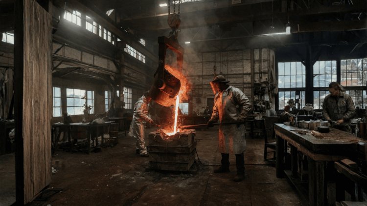
The Traditional
Trial-and-Error Era
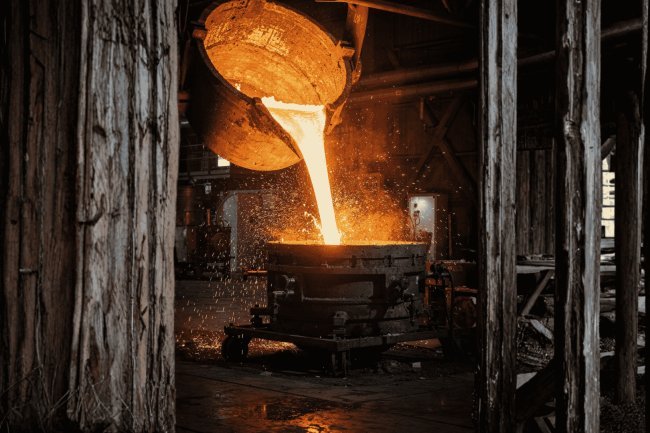
For generations, gray iron foundries relied almost entirely on practical experience, accumulated craftsmanship, and empirical design rules. Skilled foundry engineers learned to identify shrinkage-prone regions, determine riser placement, and develop gating layouts through observation and experience rather than predictive analysis. While this approach produced serviceable castings, it carried substantial hidden costs in material consumption, development time, and manufacturing risk.
Core Limitations of Traditional Methods
The Hidden Costs of Convention
To minimize the risk of shrinkage defects, foundries routinely adopted conservative design philosophies. Risers were intentionally oversized to guarantee feeding performance, often sacrificing metal yield to protect casting integrity. While effective from a quality standpoint, this approach significantly increased material consumption and remelting requirements.
Product development also proceeded through a lengthy sequence of physical trials. Each revision required new tooling adjustments, fresh mold preparation, production pours, metallurgical analysis, and post-casting inspection before subsequent improvements could be implemented.
Major Sources of Inefficiency
Metal Often Allocated to Risers
In many traditional gray iron casting operations, riser systems consumed a substantial portion of the poured metal volume, reducing overall process efficiency and increasing remelt costs.
The Visibility Problem
The greatest limitation of traditional foundry practice was the inability to observe internal casting behavior during mold filling and solidification. Once molten metal entered the mold cavity, the entire process became effectively invisible until shakeout and inspection were completed.
Engineers could not directly observe thermal gradients, monitor solidification front progression, evaluate feeding effectiveness, or determine precisely where shrinkage cavities and porosity were developing inside the casting.
Critical Information That Remained Hidden
Thermal Gradients
No practical method existed for visualizing temperature evolution throughout complex three-dimensional castings.
Solidification Progress
Engineers could not watch the growth of the solidification front or evaluate feeding paths in real time.
Defect Formation
Porosity and shrinkage cavities remained hidden until extensive inspection or machining occurred.
Root Cause Analysis
Diagnosing problems often required sectioning completed castings and working backward from observed defects.
Discovery Often Occurred After Machining
Internal shrinkage and porosity defects frequently remained undetected until expensive machining operations exposed flaws hidden beneath otherwise acceptable surfaces.
The Physical Trial Loop
Traditional Development Workflow
Consequences of Trial-and-Error Development
But Visibility Was Missing
Traditional foundry expertise provided valuable guidance, yet critical solidification phenomena remained hidden inside the mold and largely inaccessible to direct analysis.
Physical testing and empirical process adjustments.
Quantitative simulation before physical production.
Platforms such as ProCAST, SOLIDCast, and MAGMASOFT brought computational fluid dynamics and finite element heat-transfer analysis directly to the casting engineer's workstation.
Flow simulation models molten gray iron as it enters and fills the mold cavity, allowing engineers to visualize the advancing metal front and identify filling-related risks.
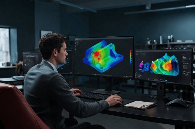
After filling, the heat-transfer solver follows solidification throughout the casting. Areas where the solidification front converges last are identified as potential hot spots and high-risk zones for shrinkage porosity.
Simulation transforms casting development from physical experimentation into a measurable, visual, and predictive engineering workflow.
Mold Filling & Turbulence Detection
Thermal Hot Spot Identification
From Geometry to Decision
As gray iron cools through the eutectic range, austenite and graphite precipitate simultaneously, releasing latent heat. Advanced micro-models track this evolution in real time, preventing errors in predicted solidification times and hot spot locations.
Graphite flake precipitation generates volumetric expansion that counteracts shrinkage. Modern tools simulate this self-feeding mechanism, reducing riser requirements by 15–25% in production castings.
The Chvorinov modulus (volume/surface area) governs solidification time. Advanced platforms compute 3D modulus fields across complex geometries, replacing manual calculations and revealing feeding requirements.
Micro-modeling connects process parameters directly to mechanical properties, enabling defect-free, efficient, and high-performance gray iron castings.
Micro-Modeling Gray Iron Casting
Phase Transformation & Latent Heat Modeling
The Graphitic Expansion Advantage
Chvorinov Thermal Modulus Mapping
Microstructure Parameter Prediction
Modern solidification simulation transforms casting optimization from a trial-and-error exercise into a systematic engineering discipline. Rather than relying on experience alone, engineers can now design thermal environments inside the mold that promote directional solidification, maintain effective feeding paths, and eliminate shrinkage-related defects before production tooling is ever manufactured.
Exothermic and insulating riser sleeves are selected using simulation-derived thermal modulus calculations to ensure risers remain molten longer than surrounding sections. By maintaining a liquid reservoir after adjacent regions begin solidifying, the riser continues feeding metal into contracting areas and prevents shrinkage cavity formation.
Simulation enables engineers to determine the optimal sleeve material, dimensions, and position with precision, removing the traditional dependency on oversized safety factors and conservative riser sizing practices.
Chills are strategically positioned using simulation-generated hot-spot maps. These dense metallic inserts extract heat rapidly from targeted areas, promoting earlier solidification and eliminating isolated hot zones that otherwise become susceptible to porosity development.
Simulation verifies the effectiveness of every proposed chill configuration before manufacturing begins, allowing optimization without expensive tooling modifications or physical trials.
Modern foundries increasingly treat mold materials as active thermal-control tools rather than passive containment media. Different molding materials possess unique thermal diffusivity characteristics that directly influence cooling rates throughout the casting.
Advanced simulations evaluate chromite, zircon, ceramic-coated, and silica-based molding systems to determine how localized material changes affect temperature distribution and solidification behavior.
Function as thermal chills that promote rapid heat extraction and localized solidification acceleration.
Act as thermal blankets that slow cooling and extend feeding opportunities where needed.
One of the most transformative benefits of simulation is iteration speed. Tasks that previously required weeks of physical pattern modifications, multiple pours, sectioning studies, and destructive testing can now be completed through virtual experimentation.
Typical casting simulations, including meshing, filling analysis, solidification calculations, and result evaluation, can often be completed within a few hours, enabling engineers to evaluate dozens of alternatives in a single work week.
Significant reduction in physical development cycles.
Improved yield through optimized feeding design.
Virtual studies replace weeks of physical experimentation.
Every riser, chill, sleeve, and mold-material decision can be engineered around measurable thermal behavior to create predictable and repeatable casting quality.
Modern casting optimization is fundamentally different from historical development practices. Armed with advanced solidification simulation, engineers can intentionally shape thermal gradients, feeding pathways, cooling rates, and microstructure evolution long before production begins. Exothermic risers, chill placement, mold material selection, and feeding-system geometry are no longer determined through conservative assumptions or repeated shop-floor experiments. Instead, they are guided by quantitative thermal analysis and validated predictive models. The result is higher casting yield, lower scrap rates, fewer prototype iterations, reduced development costs, and dramatically faster product launches. Simulation transforms casting optimization from empirical adjustment into a precise engineering discipline built on measurable physical principles.
Engineering the
Perfect ProcessFour Optimization Strategies
Exothermic Riser Sleeves
Advantages of Simulation-Guided Risers
Chill Placement Optimization
Chill-Driven Solidification Control
Mold Material Engineering
Thermal Engineering Through Mold Materials
High-Conductivity Materials
Insulating Materials
Rapid Iterative Refinement
Modern Optimization Workflow
Fewer Prototype Iterations
Less Riser Metal
Per Design Loop
By Design, Not By Luck
The Best Casting Process
Is Not Discovered Through Trials.
It Is Engineered Through Prediction.
Every major process decision can be evaluated digitally before a mold is rammed or a ladle is tapped, shifting development from sequential physical experimentation toward connected computational engineering.
Advanced foundries connect thermodynamic databases, solidification kinetics models, and 3D flow simulation into a single computational workflow.
Couple thermal simulation outputs with structural FEA to predict dimensional deviation before machining.
Train surrogate models on simulation datasets to accelerate optimization and enable real-time process parameter recommendations.
Link simulation models with production sensor data to continuously refine predictive accuracy during real pours.
Simulation-optimized conformal cooling channels become possible through 3D-printed mold inserts.
The foundry of the future is built first in the digital domain, where every pour is perfected before it happens.
The transition from foundry art to foundry science is no longer a distant aspiration — it is an available, proven, and commercially justified reality.
The Virtual Foundry Model
Co-Optimize Instead of Adjusting Sequentially
The Next Foundry Stack
Residual Stress & Distortion Prediction
Machine Learning-Assisted Optimization
Digital Twin Integration
Additive-Manufactured Tooling
What's Your Reaction?