Thermal Cycling of Permanent Casting Dies
Why repeated heating and cooling decides how long a permanent mold lasts, and how foundries can predict and control it. Die life depends on what happens between the hottest and coolest parts of each casting cycle. Molten metal heats the cavity surface rapidly; cooling and spray then remove that heat. Repeated temperature gradients load the die long before visible cracks appear.
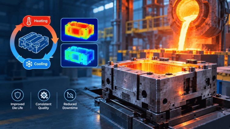
WHAT THERMAL
CYCLING DOES TO A DIE
Every shot heats the die surface sharply, then spray and cooling pull it back down. The surface tries to expand while the cooler core resists. During cooling, the strain changes again, creating a repeated thermo-mechanical load. Over time, these cyclic thermal stresses become one of the primary drivers of die deterioration and reduced tooling life.
One Production Cycle Creates A Complete Stress Event
Repeated Expansion & Contraction
Every casting shot dramatically changes the thermal state of the die surface. The exposed cavity wall experiences rapid heating while the cooler internal body of the die resists expansion. During cooling and spray application, the thermal strain reverses direction. This repeated expansion and contraction creates cyclic thermo-mechanical loading that continuously acts on the die throughout production.
From Strain To Heat Checking
Micro-Crack Initiation
Crack Growth
Heat Checking Network
Over thousands of shots, repeated thermo-mechanical loading can initiate fine surface cracks. These cracks may gradually deepen and interconnect, forming characteristic heat-checking patterns. Growth accelerates in areas where strong temperature gradients coincide with stress concentration features within the die geometry.
Damage Concentrates Locally
Sharp Corners
Stress concentrations make corners highly susceptible to crack initiation.
Abrupt Geometry Changes
Sudden section transitions amplify thermal stresses.
Gate Region
Localized turbulence, heat flux and metal interaction accelerate wear.
Thermal Gradient Zones
Regions with large temperature differences experience greater fatigue loading.
Thermal Cycling Is Not The Only Mechanism
Warping
Uneven heating may distort die geometry over time.
Soldering
Metal adhesion can accelerate local surface deterioration.
Erosion
High-velocity metal flow gradually removes surface material.
Evaluate The Entire Damage Pattern
Inspect the cavity surface, gate region and abrupt geometry changes together, rather than treating every mark as the same failure mode. Heat checking, soldering, erosion, thermal fatigue and distortion often interact and should be analyzed as a connected system of damage mechanisms.
Expansion & Contraction
The continuous alternation between thermal expansion and contraction drives the fatigue process that ultimately limits die service life.
Thermal Cycling Is A
Progressive Damage Process,
Not A Single Event.
Every casting shot creates a heating and cooling cycle that loads the die mechanically through differential expansion and contraction. Over thousands of production cycles, this repeated thermo-mechanical strain initiates heat-checking cracks, promotes crack growth and concentrates damage in high-stress regions such as sharp corners, gate locations and abrupt geometry transitions. Combined with warping, soldering and erosion effects, thermal cycling becomes one of the most important factors controlling die life, maintenance frequency and long-term production quality.
Die life is shaped by the interaction of heat input, heat removal and the die’s resistance to repeated strain. Changing one setting can shift the thermal balance elsewhere, so these drivers should be reviewed as a connected system.
Metal temperature sets the heat input. Even preheat reduces the initial temperature difference between the cavity surface and the die body, limiting severe startup transients.
These control how much heat leaves between shots. Inconsistent timing, excessive local spray or uneven coating can create cold patches beside persistent hot zones.
Select these together for hot strength, toughness and resistance to surface damage. Hardness alone does not describe thermal-fatigue performance.
Channel position and section thickness govern heat paths. Uneven heat removal and abrupt thickness changes encourage gradients and local stress concentrations.
Connected system: Heat input, heat removal, material properties and geometry should be evaluated together when assessing die life.
WHAT DRIVES DIE LIFE
Pouring Temperature and Die Preheat
Cycle Time, Spray Cooling and Coating Practice
Die Material, Hardness and Surface Treatment
Cooling Channel Layout and Wall Thickness
Use casting simulation to compare die designs and operating conditions before tooling. Its linked view brings together temperature, stress, and filling behavior—not just a temperature map.
Illustrative temperature field, not a computed result. Actual temperatures depend on the die, alloy, and cycle.
Shows cooling, hot spots, and gradients across the die over the cycle—revealing where heat accumulates and how the thermal field evolves from fill to ejection.
Assesses thermo-mechanical stresses and dimensional stability under the predicted thermal loading—linking the thermal field to mechanical consequences in the die.
Reveals filling patterns and potential erosion zones that load the die unevenly—identifying where melt impingement and flow asymmetry concentrate wear.
PoligonSoft is an all-in-one FEM-based tool for permanent mold casting. Use realistic boundary conditions and check predictions against measured die behavior.
Predict It Before
Cutting SteelCooling, hot spots, gradients across the cycle.
Thermo-mechanical loads and dimensional stability.
Filling patterns and erosion zones.
compare die designs and operating conditions with a linked view
of temperature, stress, and filling behavior.
A stronger die material cannot compensate indefinitely for an unstable cycle or poorly balanced cooling.
Bring the die to a suitable operating condition before production and hold a stable temperature through the run. Review restart practice after interruptions, when the thermal balance has changed.
Balance cooling channels, round sharp corners and smooth thickness changes. Review hot spots and stress concentrations together so a cooling change does not simply move the problem.
Control spray volume and timing consistently.
Inspect vulnerable regions on schedule, record damage progression, and stress-relieve according to the die material and an approved maintenance procedure.
Reduce local extremes and keep the cycle repeatable. Start with temperature stability, then address the places where heat and stress concentrate. Preheat evenly, balance the heat paths, and control spray and maintenance practices consistently. A stronger die material cannot compensate indefinitely for an unstable cycle or poorly balanced cooling.
DESIGN DECISIONS AND SHOP-FLOOR CONTROL
Practical Ways
To Extend Die LifePreheat Evenly
Balance The Heat Paths
Solve The Entire Thermal System
Control Spray And Maintenance
Monitor Before Failure
For Licensing, Training And Support, Contact Our Team
Extend Die Life By
Stabilising Temperature,
Balancing Heat Flow,
And Maintaining Control.
What's Your Reaction?