Flow Separation in Casting Runners: From First Split to Zero-Defect
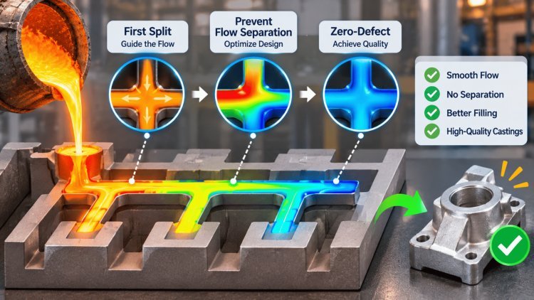
Understanding how molten metal moves through runner systems is the difference between a flawless casting and a scrapped part. Flow separation — the moment a metal stream loses cohesion and breaks apart inside the runner — is one of the most consequential phenomena in casting engineering. It happens in fractions of a second, but its effects echo through every stage of solidification. This presentation unpacks the physics, the geometry triggers, the downstream defect chain, and how simulation driven design can eliminate these failure modes before a single tool is cut.
What Runners Must Do —
and What Goes Wrong
A runner system carries a deceptively simple mandate: deliver molten metal from the sprue to every gate at the right velocity, the right temperature, and the right pressure — simultaneously, every time. When that mandate fails, the consequences cascade across the entire casting. Understanding what runners are supposed to do is inseparable from understanding how they break down.
The Ideal Runner Function
In PoligonCast's flow-and-filling simulation view, velocity and temperature fields are the two master variables.
A well-designed runner maintains laminar or near-laminar flow, keeps the melt front continuous and thermally uniform, and delivers metal to the cavity with minimal pressure loss.
Every geometric choice — cross-section shape, taper angle, branch ratio — either supports or undermines that goal.
Uniform velocity distribution prevents premature solidification at thin-walled cavity sections
Temperature consistency across the melt front eliminates cold-shuts before they begin
Controlled pressure distribution ensures simultaneous, balanced cavity fill
When Flow Becomes Unstable
Flow instability in a runner isn't a single event — it's a cascade.
The moment the melt stream loses cohesion, a chain of downstream consequences is set in motion.
Turbulent flow entrains air pockets, shears oxide films into the bulk metal, and creates localized velocity spikes that erode mold surfaces. These effects don't stay in the runner; they travel directly into the cavity.
Velocity Field
Controls where turbulence initiates and whether the melt front advances continuously or intermittently into the cavity.
Temperature Field
Determines premature freeze-off risk and cold-shut formation — defects that begin in the runner, not the gate.
Pressure Distribution
Governs fill balance across multiple gates and drives aspiration risk at every cross-section change.
The runner is not a passive conduit. It is an active flow-engineering component, and treating it as an afterthought is one of the most expensive mistakes in casting process design. Control velocity, temperature, and pressure correctly in the runner, and the entire casting process becomes more stable, predictable, and defect-resistant.
Flow separation does not occur randomly. It is the predictable result of specific geometric configurations interacting with fluid-dynamic thresholds. Every bend, branch point, cross-section change, and gate transition in the runner system is a potential separation site — and the engineering challenge is to design those features so the melt navigates them without losing cohesion.
The overall architecture of the gating system — how sprues, runners, and gates are arranged and proportioned — determines the fundamental character of the flow. Poorly proportioned systems create velocity imbalances between gates, force the melt to accelerate through undersized sections, and generate recirculation zones at every branch point.
Initiates at abrupt cross-section changes and sharp bends where the boundary layer separates from the wall.
Occurs in runner segments running below atmospheric pressure — common in top-gated systems with oversized runners.
Accelerates wherever turbulence brings fresh metal surface into contact with atmosphere or mold gases.
Concentrates at impingement points where the jet from the sprue strikes the runner floor.
Explore the full engineering context for gating system design at PoligonCast Engineering, where runner sizing logic, fill simulations, and regime analysis tools are documented in depth.
The Reynolds number is the central dimensionless parameter governing whether runner flow is laminar, transitional, or turbulent. For most nonferrous casting alloys, engineers target a Reynolds number below 20,000 in the runner — a threshold beyond which boundary-layer detachment and stream breakup become statistically inevitable.
Ideal but rarely achievable at commercial fill rates.
Practical target zone for most aluminum and copper alloys.
Oxide entrainment and stream breakup become dominant failure mechanisms.
Achieving the target regime requires coordinated control of metal velocity, runner hydraulic diameter, and alloy viscosity — none of which can be optimized in isolation.
Use the HotFlo runner sizing calculator to validate cross-section geometry against Reynolds number targets before committing to tooling.
Distribute flow across a wide gate width by gradually expanding the runner cross-section. When designed correctly, they reduce velocity and transition turbulent flow toward laminar before entry. When oversized or abruptly tapered, they create reverse-flow recirculation zones that trap oxides at the gate lip.
Introduce the melt tangentially into a cylindrical or prismatic cavity, inducing a controlled swirl that separates dross toward the center by centrifugal action. The engineering tradeoff is managing the velocity gradient between the inner and outer wall of the curved section to prevent secondary separation.
Use an enlarged cross-section or chamber immediately downstream of the sprue base to decelerate the initial melt surge and absorb the hydraulic shock of fill initiation. They are particularly effective at preventing the first-shot turbulence burst that contaminates the leading melt front with entrained oxides.
Incorporate in-runner restrictions that throttle flow at branch points, equalizing fill pressure across multiple gates feeding a single cavity. Critical for multi-gate tooling where unbalanced fill creates race-tracking and premature freeze-off in slower-filling sections.
Where Flow Separation Begins: Geometry + Regime Thresholds
Gating System Architecture
Turbulence
Air Aspiration
Dross Formation
Mold Erosion
Reynolds Number and the Flow Regime Battle
Laminar Regime
Transitional Regime
Turbulent Regime
Controlling the Target Flow Regime
Runner Building Blocks and Their Flow Effects
Fan Gates
Tangential Runners
Shock-Absorber Runners
Gated Runners
Flow separation in the runner is not an isolated event. It initiates a defect chain that propagates through filling, solidification, and final mechanical properties. Mapping this chain completely—from the first instability in the runner to the final crack susceptibility in the solidified part—is essential for root-cause engineering rather than symptomatic correction.
Stream breakup and loss of cohesion are the first consequences of flow separation. When the melt stream detaches from the runner wall, it creates a free-surface jet inside the runner—a surface exposed to the mold atmosphere and highly reactive in aluminum, magnesium, and copper alloys.
The damage initiated during fill manifests as solidification and structural defects that determine the mechanical integrity of the finished casting. Because these defects originate during fill, they cannot be corrected by optimizing solidification conditions—the root cause is upstream in the runner.
The Downstream Damage Chain:
Turbulence to DefectsStream breakup starts the chain.
Fill-phase damage becomes structural damage.
create defects that no post-process—heat treatment, HIP, or machining—
can fully eliminate. The only effective intervention is upstream,
in the runner geometry itself.
The economics of casting tooling make pre-production validation non-negotiable. A single runner modification after tool completion can cost more than the entire simulation campaign that would have identified the problem virtually. Modern integrated solvers eliminate this risk by allowing engineers to iterate runner, gate, and riser geometry exhaustively — before any metal is poured or steel is cut.
Virtual fill simulation traces the melt front from sprue entry to last-to-fill cavity section, flagging velocity spikes, recirculation zones, and air-entrapment pockets at every geometry transition. Engineers can iterate runner cross-sections, taper ratios, and branch angles until the velocity field is smooth and the Reynolds number stays within the transitional-laminar target band throughout fill.
Runner sizing tools can be used in conjunction with simulation to pre-dimension geometry before the first solver run.
Linked thermal solvers track how the fill-induced temperature distribution evolves during solidification, identifying hot spots, shrinkage cavity locations, and porosity risk zones. Because the thermal initial condition is inherited directly from the fill simulation, the solidification prediction reflects the actual — not idealized — state of the melt at end-of-fill.
This coupling is what makes the defect prediction actionable: engineers see exactly which runner modification eliminates which solidification risk.
The final solver layer applies thermo-mechanical analysis to the solidifying casting, computing residual stress fields and identifying crack-susceptible locations driven by thermal gradients inherited from the fill and solidification stages.
This closes the simulation loop: a runner geometry change propagates through fill → solidification → stress in a single integrated workflow, giving engineers a complete risk picture for every design iteration — all before tooling investment is committed.
Start your simulation-driven design process with PoligonCast's integrated solvers — covering flow, porosity prediction via cooling analysis, and thermo-mechanical stress in a single unified platform.
For runner and gate cross-section pre-sizing, the HotFlo runner calculator provides a fast analytical baseline before committing to full CFD runs.
For deeper engineering context on gating system design methodology, visit the PoligonCast Engineering resource hub.
The path to zero-defect casting outcomes begins not at the furnace, but at the runner geometry — and simulation is what makes that path visible before production ever begins. For more details contact with us.
Validate Before You Cut Steel
Fill Behavior & Turbulence Mapping
Solidification & Porosity Prediction
Thermo-Mechanical Stress & Crack Risk
What's Your Reaction?