Eulerian–Lagrangian Coupling in Casting Simulation
A technical deep-dive into the mathematical frameworks, interface methods, and industrial implementations that enable accurate, physically faithful simulation of the casting process — from mold filling through solidification and beyond.
Why "Couple Two Worlds"?
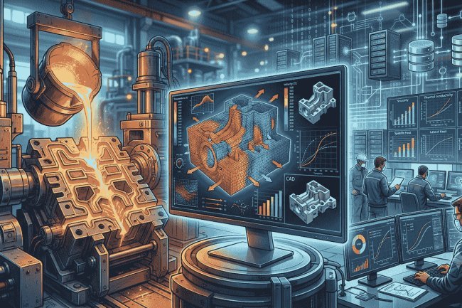
Casting simulation operates at the intersection of two fundamentally different mathematical perspectives. During mold filling and solidification, engineers must simultaneously track moving interfaces, evolving material boundaries, fluid flow, heat transfer, and species transport. No single numerical framework handles all of these requirements optimally. Modern casting simulation succeeds by combining Eulerian and Lagrangian concepts into one integrated computational strategy.
The Fundamental Challenge
Moving Melt Front
Continuously evolving free surface geometry.
Solidification Front
Dynamic liquid-to-solid transformation boundary.
Transport Physics
Momentum, heat, and species transport.
The Core Tension
Tracks Moving Boundaries Naturally
Free surfaces and solidification fronts remain attached to the material. Boundary motion is represented with excellent geometric fidelity and minimal interface smearing.
Severe Mesh Distortion
Large deformations during mold filling stretch and distort the mesh, eventually leading to poor element quality and numerical instability.
The Eulerian Perspective
Major Advantage
Fixed computational grids handle very large deformations effortlessly while providing robust transport calculations.
Main Challenge
Numerical diffusion can blur interfaces and smear free-surface details important for defect prediction.
Why Interface Accuracy Matters
The most important casting defects originate at moving interfaces. If interface position is inaccurate, defect predictions become unreliable regardless of how accurate the rest of the simulation may be.
Couple Both Worlds
The reference frame determines which physics can be represented faithfully, where numerical errors accumulate, and what computational cost the simulation must carry.
The grid or material points move with each fluid or solid parcel through space and time.
Material flows through a stationary computational grid that does not deform with the process.
Mesh velocity is selected independently from material velocity to balance interface fidelity and bulk stability.
Mesh moves with material to preserve geometric interface accuracy.
Mesh remains fixed or uses an intermediate velocity to limit distortion.
Convection, diffusion, and interface representation are coupled deliberately.
In casting applications, an Eulerian solver may handle convection and diffusion on a background grid while a Lagrangian interface representation or capturing field is advected and periodically reinitialized. The accuracy of the complete method depends on how these layers exchange information.
Frames of Reference
as a Design ChoiceFollow the material
Hold the grid fixed
Move where useful
Interface precision versus deformation tolerance
The numerical art is in the coupling.
It is the architecture of the simulation.
Tracking approaches explicitly represent the interface as a conforming mesh boundary. ALE methods move the mesh to follow the free surface, achieving near-geometric precision. Best suited for smooth, moderately deforming surfaces like early gravity filling. Limitation: large topological changes require remeshing, introducing interpolation errors and overhead.
Capturing methods embed the interface implicitly in a field variable on a fixed grid. VoF tracks fractional volumes, level-set uses signed distance functions, and phase-field diffuses the interface. These methods handle merging, splitting, and splashing without remeshing, making them dominant in industrial casting solvers. Tradeoff: finite numerical thickness and careful curvature computation are required.
Interface method choice directly affects defect prediction quality:
High-resolution capturing methods (HRIC-stabilized VoF, conservative level set) are industrial standards. Phase-field methods are transitioning from research to production, especially for solidification-front and grain-structure prediction.
The accuracy of free-surface and solidification-front representation bounds defect prediction quality — making interface method selection a first-order engineering decision.
How Interfaces Get Handled in Practice
Interface Tracking — ALE Methods
Interface Capturing — VoF, Level Set, Phase Field
Casting-Specific Priorities
Modern commercial casting simulation systems translate decades of academic research into production-ready engineering tools. STAR-Cast represents one of the most mature implementations of Eulerian-Lagrangian coupling, integrating flow physics, heat transfer, free-surface tracking, solidification, gas behavior, and defect prediction within a unified industrial framework capable of supporting real-world casting operations.
STAR-Cast simultaneously resolves three interacting phases: the surrounding gas atmosphere, the flowing liquid metal, and the emerging solid shell. Mass, momentum, energy, and phase interactions are solved together at each timestep, creating a tightly coupled representation of the casting process.
Free-surface tracking is performed using the High-Resolution Interface-Capturing (HRIC) scheme within a Volume-of-Fluid framework. This bounded compressive approach preserves sharp metal-gas interfaces while minimizing numerical diffusion and interface smearing.
Surface tension forces and wetting-angle boundary conditions are applied at the contact line, allowing accurate prediction of meniscus formation, thin-section filling behavior, and capillary-driven flow effects.
Industrial Implementation:
STAR-Cast's Coupled Flow–
Solidification CoreWhat Makes STAR-Cast Different?
Multiphase Coupled Core
Three Co-Existing Phases
Physics Solved Every Time Step
Free Surface & Gas Handling
Explicit Gas Behavior Modeling
Surface Physics Included
Rotating Frames & Moving Grids
Coupled simulation has become an industrial workhorse. The next frontier is tighter, bidirectional integration between macro-scale flow and the microstructure physics that ultimately controls part performance.
A rotating-frame Eulerian solver combined with free-surface capture can connect rotational speed and fill rate to radially stratified melt distribution, internal porosity bands, and downstream metallurgical quality.
Coupled defect maps can be compared with destructive inspection data from production parts, enabling virtual die and process optimization before the first pour.
Feed stress and distortion back into flow so mold-wall deformation and filling influence one another across different timescales.
Connect macro thermal and compositional fields to grain-scale models, phase diagrams, and columnar-to-equiaxed transition criteria.
Couple thermal strain, mush-zone permeability, and interdendritic feeding at the moving solidification front.
The Payoff—and the Frontier
One coupled workflow, from melt to quality
Coupling is essential to the prediction.
Closing the loop to final properties
It will connect processing parameters to microstructure and mechanical performance.
What's Your Reaction?