Mold Surface Roughness and Metal Flow Behavior
An in-depth exploration of the mold-shell interface, thermal dynamics, and advanced computational strategies for eliminating surface defects in direct chill casting of aluminum alloys.
The Casting Challenge:
Why Surfaces Fail
The aluminum manufacturing industry overwhelmingly relies on direct chill (DC) casting to produce large-format ingots and billets. Despite decades of refinement, surface defects remain a persistent and costly barrier to producing high-quality, ready-to-process product. Understanding the root causes of these failures at the mold-metal interface is the first step toward eliminating them.
Three Mechanisms Drive Surface Quality
Non-Uniform Heat Extraction
Inconsistent contact between the molten metal and the mold wall creates localized zones of rapid and slow cooling. This thermal asymmetry directly drives differential solidification rates, leading to internal stress concentrations and surface waviness that propagate throughout the solidified shell.
How Contact Variation Becomes a Surface Defect
Air-Gap Formation
As the solid shell contracts away from the mold wall, microscale air gaps nucleate and grow at the interface. Because air is a poor thermal conductor compared to liquid aluminum or the mold material, these gaps act as insulating barriers, dramatically reducing heat extraction efficiency and creating thermal gradients that promote cracking.
A Microscopic Gap Creates a Macroscopic Thermal Effect
Inverse Segregation
Shrinkage-induced fluid flow draws solute-rich liquid toward the solidification front and the casting surface. This enrichment of alloying elements at the outer skin produces non-uniform solute distribution, surface ripples, and a chemically heterogeneous layer that is mechanically inferior and requires removal before downstream processing.
Solute Moves Toward the Surface
The Outer Layer Loses Uniformity
The Cost of Surface Failure
The cumulative impact of these phenomena forces manufacturers into expensive remediation — typically scalping and milling several millimeters from the ingot surface before rolling or extrusion can begin.
Surface Defects Create a Waste Chain
Surface Quality Becomes a Yield Problem
Every millimeter removed from an ingot represents metal that was melted, alloyed, cast, cooled, and handled only to be machined away before downstream processing.
Control the Mold-Shell Interface
The fundamental goal of modern casting research is to control the mold-shell interface to eliminate these defects at the source, reducing material waste and energy consumption.
Eliminate the Cause Before Removing the Surface
Surface Quality
Is Created at the
Mold-Shell Interface.
Surface failure in direct chill aluminum casting emerges from a tightly connected set of thermal, mechanical, and metallurgical mechanisms. Non-uniform mold contact produces uneven heat extraction and differential shell growth. As the shell contracts, microscale air gaps further reduce local heat transfer and intensify thermal gradients, increasing stress and cracking susceptibility. At the same time, shrinkage-induced flow can transport solute-rich liquid toward the solidification front and outer surface, generating inverse segregation, surface ripples, and chemically heterogeneous material. The cumulative result is a surface layer that frequently requires several millimeters of scalping or milling before rolling or extrusion. Modern casting research therefore focuses on controlling the mold-shell interface itself, preventing unstable heat transfer, air-gap formation, and surface enrichment at their source so manufacturers can reduce material removal, energy consumption, and downstream processing cost.
Heat extraction during solidification is fundamentally governed by the quality of thermal contact between the molten metal and the mold wall. This contact is quantified by the interfacial heat transfer coefficient (IHTC), which depends on surface topology, applied pressure, metal head, and the evolving gap geometry.
At the onset of casting, intimate contact between the liquid meniscus and the mold surface yields high IHTC values. However, this condition is inherently transient and unstable. As solidification progresses and the nascent shell begins to carry thermal and mechanical loads, the IHTC degrades rapidly.
Air-gap formation is not instantaneous—it is a progressive process driven by the accumulation of thermal stress within the growing solid shell. As the shell thickens, the differential between the hot interior and the cooler mold-contact surface generates compressive and tensile stress fields.
During solidification, the solid phase is typically purer than the liquid, forcing solute atoms into the residual melt ahead of the front. Simultaneously, volumetric shrinkage of the solidifying metal draws this solute-enriched liquid outward through the mushy zone toward the surface.
The interfacial physics chain—liquid contact, shell formation, air-gap nucleation, and inverse segregation—governs heat extraction, surface quality, and near-surface chemistry in every casting process.
The Physics of the Interface
IHTC: high at contact, degrades with separation.
Stress exceeds contact pressure → separation.
Solute-enriched surface layer forms.
sets the trajectory for heat extraction, surface defect formation,
and near-surface segregation throughout solidification.
Modern research is moving beyond accepting interfacial contact degradation as an unavoidable constraint. Instead, mold surface topography is being engineered to modulate heat transfer, control gap formation, and suppress segregation-driven defects.
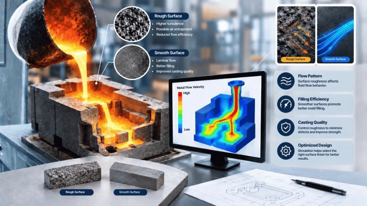
The most promising approach employs sinusoidal groove textures machined into the mold face to fundamentally alter the mechanics of shell-mold interaction. These grooves act as a distributed micro-radiator at the metal-mold interface, creating a periodic and controlled topography that makes thermal behavior more uniform and predictable.
The peaks of the grooves maintain intimate contact with the solidifying shell, helping preserve a more consistent effective contact area.
The valleys create controlled micro-cavities that remain geometrically constrained rather than growing into large thermally insulating air gaps.
The repeating groove geometry effectively tiles the interface with known unit cells, making the system more amenable to analytical and computational modeling.
Prone to uncontrolled gap formation and uneven thermal contact.
Periodic geometry creates controlled thermal behavior at the shell-mold interface.
Parametric studies have demonstrated that mold wavelength — the spatial period of the sinusoidal texture — is the single most critical geometric parameter. Wavelengths below approximately 5 mm consistently produce more stable, uniform solidification front geometry.
Groove amplitude — the peak-to-valley height — presents a fundamental engineering trade-off. Increasing amplitude enhances the radiator effect: more surface area becomes available for heat transfer per unit length of mold, while the groove geometry promotes more aggressive convective exchange with the mold body.
This translates directly to higher average IHTC values and faster, more uniform solidification. However, higher amplitudes also exert a stronger geometric influence on the developing solid-liquid front.
More surface area and stronger thermal exchange can increase average IHTC and promote faster, more uniform solidification.
Deep grooves can distort the solid-liquid front, introducing lateral solute gradients and stress concentrations that partially offset the thermal benefits.
Materials such as copper maximize the heat extraction benefit of groove geometry but may require different amplitude-wavelength combinations.
Materials such as iron or graphite interact differently with the groove geometry and may require alternative amplitude-wavelength combinations.
The mold topography and the mold material must be co-optimized as an integrated thermal system, not designed independently.
Engineering the Mold Topography
The Sinusoidal Groove Concept
Intimate Shell Contact
Constrained Micro-Cavities
Predictable Thermal Behavior
The Critical Role of Wavelength
Amplitude Effects and Trade-offs
Material Selection Synergies
High-Conductivity Materials
Lower-Conductivity Materials
Topography + Material = One Thermal System
Modern FEM platforms employ SUPG and PSPG stabilization techniques to accurately solve strongly convective thermal-fluid problems at the solidification front. These formulations suppress numerical oscillations, maintain solution stability, and enable simultaneous resolution of thermal transport, solute redistribution, mushy-zone flow, and latent heat evolution.
By comparing equivalent stress within the growing shell against local metallostatic pressure, simulation predicts exactly where and when shell separation from the mold will occur. Engineers use these predictions to redesign groove geometry and modify operating parameters before costly defects appear in production.
Simulation allows copper, iron, lead, graphite, and alternative mold materials to be evaluated digitally before fabrication. Engineers can compare predicted thermal histories, interfacial heat-transfer behavior, stress development, surface quality, and solute distribution while eliminating weeks of experimental trial work.
Higher metallostatic pressure increases contact force between shell and mold, delaying air-gap formation. Combined with optimized groove geometry, elevated pressure suppresses thermal degradation mechanisms that contribute to surface defects and casting quality loss.
Virtual testing powered by stabilized finite element simulation enables engineers to predict air-gap nucleation, thermal stresses, interfacial heat transfer behavior, and casting surface quality before any metal is poured. This dramatically reduces physical trial cycles, accelerates material selection, and improves confidence in final mold design.
Resolving Mold-Metal Interface Physics
Stabilized Finite Element Simulation
Predictive Gap Nucleation Modeling
Virtual Mold Material Testing
Melt Pressure & Geometry Optimization
Engineering Impact
The field of mold-interface engineering has undergone a fundamental transformation. What was once a domain of empirical trial-and-error, guided by accumulated shop-floor experience and qualitative metallurgical intuition, has become a rigorous predictive design discipline grounded in coupled physics simulation and inverse optimization methods.
Inverse design techniques now allow engineers to specify a desired microstructural outcome — a target grain size distribution, a maximum allowable segregation depth, or a prescribed surface roughness — and work backward computationally to identify the mold topography parameters that will produce it.
This reversal of the traditional design workflow is a profound shift: rather than predicting what a given mold will produce, engineers can now prescribe what the cast surface must look like and solve for the required mold geometry.
The Future of
Precision CastingFrom Experience to Predictive Design
From Trial-and-Error to Inverse Design
Begin With the Required Outcome
Stop Asking "What Will This Mold Produce?"
What's Your Reaction?