Modeling Stainless Steel Casting Processes
A comprehensive guide to computational simulation methodologies for predicting thermal behavior, solidification patterns, microstructural evolution, and defect formation in stainless steel casting operations — enabling engineers to optimize yield and quality before a single part is poured.
The Core Problem:
Heat Transfer and Shrinkage
Decide Everything
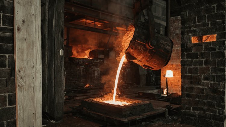
Every stainless steel casting begins as molten metal exceeding 1400°C and ends as a solid engineering component operating at ambient conditions. Between these two states lies a highly complex thermal and metallurgical journey. The extraction of heat, progression of solidification, and accommodation of volumetric contraction collectively determine whether the final casting achieves dimensional accuracy, structural integrity, pressure tightness, and required mechanical performance.
Two Governing Engineering Challenges
Thermal Modeling
Modern casting simulations calculate the temperature field throughout the complete mold-casting system as a function of both time and position. By solving heat-transfer equations while accounting for latent heat release during phase transformation, engineers gain visibility into how thermal energy moves through the casting during solidification.
These calculations reveal where heat remains trapped the longest. Such regions, commonly known as hot spots, represent the areas most vulnerable to feeding deficiencies, shrinkage formation, and internal integrity problems.
Thermal Analysis Workflow
Last To Freeze = Highest Risk
Regions that retain heat longest become the final areas to solidify and therefore demand continuous liquid feeding to avoid void formation.
Importance of Thermal Gradients
Thermal gradients govern directional solidification. When properly engineered, solidification progresses systematically from thinner sections toward feeders and risers, maintaining a continuous supply of liquid metal. This directional behavior is essential for producing sound stainless steel castings free from shrinkage-related defects.
Volumetric Shrinkage
Stainless steels typically experience volumetric contraction between 4% and 7% during solidification. As the material transforms from liquid to solid, density increases and additional metal must be supplied to compensate for the resulting volume reduction.
Modern simulation tools couple thermal calculations with density-change models, allowing engineers to determine exactly where feeding becomes insufficient and shrinkage defects are most likely to develop.
Typical Solidification Shrinkage
Even relatively small volumetric contractions generate significant feeding requirements throughout complex stainless steel castings.
Shrinkage Defect Types
Micro-Porosity
Small distributed voids that form between dendritic structures when localized feeding becomes inadequate.
Macro-Porosity
Larger, discrete cavities that develop when substantial regions lose access to liquid metal feeding.
Consequences of Shrinkage Defects
The Complete Casting Picture
Thermal behavior determines where shrinkage wants to occur, while feeding efficiency determines whether shrinkage defects actually form.
Simulation-Based Defect Prediction
Eliminate Risk Before Tooling
Accurate prediction of thermal hot spots and shrinkage locations empowers engineers to optimize risers, feeders, and casting geometry long before physical tooling is manufactured.
Successful Stainless Steel Castings
Are Ultimately Determined By
Heat Extraction And Feeding Efficiency.
The central challenge of stainless steel casting is managing the interaction between thermal evolution and volumetric shrinkage. Heat transfer governs where solidification occurs and where hot spots develop, while volumetric contraction creates an unavoidable demand for liquid metal feeding. Thermal simulations identify regions most vulnerable to feeding deficiencies, and shrinkage models determine whether available liquid metal can compensate for local volume changes during solidification. Together, these coupled analyses provide detailed predictions of porosity formation, internal soundness, and final component quality. By identifying these risks before tooling is cut, foundries can dramatically reduce development costs, shorten qualification programs, and reach first-pass casting success with far greater confidence.
Accurate simulation models must reflect the complete investment-casting sequence. Wax preparation, shell construction, preheating, pouring, solidification, and shell removal each contribute conditions that affect the final component.
Precision wax replicas of the desired part are injection-molded and assembled onto a central sprue to form a “tree” or cluster. Gates and runners are incorporated to control metal flow paths during pouring.
The wax cluster is repeatedly dipped into ceramic slurry and coated with refractory stucco, typically over 8–12 layers, creating a shell approximately 6–10 mm thick.
The ceramic shell is placed in an autoclave or flash furnace to melt and drain the wax, leaving a hollow ceramic mold. The mold is then preheated to prevent thermal shock during pouring and to maximize metal fluidity.
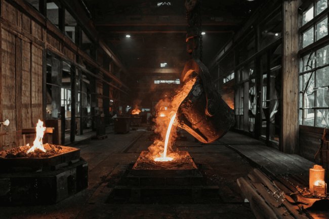
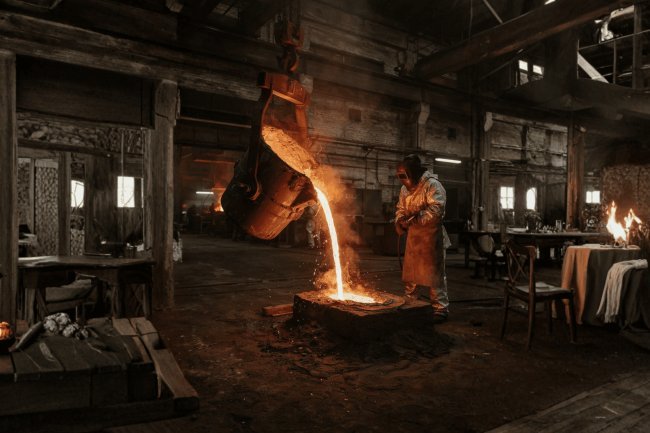
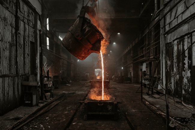
Molten stainless steel — typically at 1540–1600°C — is poured into the preheated ceramic mold under gravity or vacuum-assisted conditions.
The filled mold cools under ambient or controlled conditions. Once solidification is complete, the ceramic shell is broken away by mechanical vibration or water blasting, revealing the cast component still attached to the runner system.
From the ceramic shell and its preheat condition to metal temperature, filling behavior, cooling, and solidification, the investment-casting timeline establishes the boundary conditions that ultimately shape the final stainless steel component.
Every Stage Becomes a Simulation Condition
Building the “Tree”
Building the Refractory Mold
Preparing the Ceramic Shell
Filling the Preheated Shell
Revealing the Final Casting
From Wax to Finished Component
Every Stage Leaves a Thermal Fingerprint
Simulation outputs reveal distinct signatures: shrinkage correlates with hot spots, gas porosity with dissolved gases, inclusions with turbulent filling.
The sprue, runner, and gate network control velocity, direction, and temperature of molten metal. Stainless steel alloys solidify across a range between liquidus and solidus. Within the mushy zone, dendrites coexist with interdendritic liquid, reducing permeability. Credible casting models must integrate defect mechanisms, feeding geometry, and mushy-zone physics to deliver actionable, real-world simulation outputs.
Where Models Need to Get Real
Defect Formation Mechanisms
Gating, Runners & Feeding Systems
Undersized gates: turbulence & oxide entrainment.
Oversized systems: wasted metal & slower solidification.
Risers must feed last-solidifying regions; simulation optimizes geometry using Niyama criteria and feed path connectivity.
Time-Dependent Solidification & Microstructure
Key factors: zone width, cooling rate, and thermal gradient — together determining grain size, dendrite arm spacing, and hot tearing susceptibility. Accurate mushy-zone modeling yields microstructural predictions aligned with mechanical properties.
Casting simulation is far more than a single numerical calculation. It is a structured engineering workflow that transforms material properties, geometry, and process parameters into actionable manufacturing intelligence. Each stage builds upon the previous one, creating a continuous loop of analysis, interpretation, and optimization that enables engineers to refine casting designs long before physical production begins.
Every simulation begins by defining the alloy system and mold materials. Engineers select casting grades such as CF8M, 316L, or 17-4PH stainless steel and specify the surrounding mold environment, whether ceramic shell, sand mold, or permanent mold construction.
Temperature-dependent thermophysical properties including density, specific heat, thermal conductivity, and latent heat are assigned to the model. The complete 3D geometry is then imported or constructed, incorporating not only the casting itself but also the entire rigging system, including sprues, runners, gates, risers, filters, and chills.
Before calculations can begin, the casting and mold volumes must be divided into a computational mesh. This process converts continuous geometry into thousands or millions of finite elements or finite-difference cells that can be solved numerically.
Mesh density is concentrated in geometrically complex regions such as thin walls, gate junctions, sharp corners, and high-gradient thermal zones. Increased refinement improves accuracy but requires additional computational resources.
Simulation accuracy scales with mesh resolution, with complex industrial castings frequently exceeding several million computational cells.
The first simulation stage models mold filling. Engineers track metal velocity, turbulence behavior, free-surface evolution, flow patterns, and temperature distribution throughout the filling process. This identifies potential defects including air entrapment, misruns, oxide formation, and premature freezing.
Once filling is completed, the model transitions automatically into solidification analysis. The software tracks latent heat release, thermal gradients, shell growth, feeding behavior, shrinkage evolution, and cooling throughout the casting-mold system until solidification is complete.
This stage is where simulation creates real engineering value. Results are visualized through temperature contours, hot-spot maps, solidification-time plots, shrinkage predictions, porosity probability maps, Niyama criterion distributions, and feeding indicators.
Regions that fail quality requirements are identified and corrected. Engineers may relocate risers, enlarge feeders, modify gate design, adjust pouring temperature, introduce chills, or alter cooling strategies before repeating the workflow.
The greatest value of casting simulation comes not from the first result, but from rapidly exploring alternative solutions until quality objectives are satisfied.
A medium-complexity investment casting simulation can typically be completed within 2–8 hours on a modern engineering workstation. This enables multiple design iterations in a single day, dramatically accelerating development compared to traditional physical prototype cycles that often require days or weeks.
Modern casting development minimizes risk by discovering and correcting problems in the digital environment before committing resources to production tooling.
Successful casting simulation is a structured engineering cycle rather than an isolated calculation. Material definitions establish physical behavior, meshing translates geometry into a solvable domain, filling and solidification simulations reveal thermal and metallurgical performance, and result interpretation drives design improvement. The workflow then repeats until quality targets are achieved. Modern software platforms allow engineers to evaluate multiple feeding systems, gating layouts, pouring conditions, and cooling strategies within a single workday. This iterative capability dramatically reduces development cost, shortens qualification timelines, minimizes scrap risk, and enables casting defects to be eliminated digitally before production begins.
Simulation Workflow:
Build, Mesh, Run,
Interpret, IterateThe Four-Step Engineering Workflow
Define Materials & Geometry
Required Model Inputs
Mesh the Domain
Typical Mesh Nodes
Run Filling & Solidification
Simulation Sequence
Interpret Outputs & Redesign
Critical Simulation Outputs
Continuous Optimization Loop
Engineering Speed Advantage
Physical Trials Second
The Power Of Simulation
Lies Not In A Single Run,
But In Fast Iteration.
The ultimate justification for investing in casting simulation is the dramatic compression of the development timeline and the measurable improvement in production economics.
Documented industry case studies across investment casting and sand casting operations confirm that virtual process development can deliver returns that far exceed the cost of software licensing and engineering time.
Hot spots, shrinkage cavities, misruns, and cold shuts can be identified and addressed before production tooling is cut or alloy is melted.
Pouring temperature, fill rate, preheat level, and riser dimensions can be varied parametrically to explore better process conditions.
Simulation creates a better-understood process that is less sensitive to natural variation and more capable of producing consistent results.
Virtual development supports demanding aerospace, medical, and industrial quality requirements before the first production run.
The real payoff of casting simulation is not simply fewer physical trials. It is the ability to learn faster, optimize systematically, reduce material waste, and enter production with a process that has already been tested virtually.
Faster Learning Cycles and Higher Yield Without Guesswork
Simulation Turns Development Into a Measurable Advantage
Development Time Compression
Move Experimentation From the Shop Floor to the Computer
Find Defects Before Production
Sweep Process Parameters
Build Process Robustness
Improve First-Run Confidence
From Guesswork to Parametric Optimization
What's Your Reaction?